Explore our dedicated comprehensive guide if you want to learn how to reduce costs and lead times in OEM projects using efficient and easy-to-integrate indicator lights.
All of us today are in contact with electronics through the devices we use on a daily basis such as smartphones, computers and household appliances. But what is inside them?
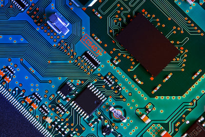
Some light indicators have an electronic board with LEDs.
This board consists of a printed circuit board and a combination of electronic components.
The Printed Circuit Board (PCB) is the base on which the copper tracks, which serve as connections between the various electronic components, are engraved using optical and chemical production processes. The electronic components, on the other hand, deal with the conduction and transformation of electricity and are chosen and positioned according to the function of the board, following essential technical standards.
In particular, inside an illuminated switch, there is a small simple circuit on which LEDs, resistors and rectifier diodes are mounted.
What are the steps involved in manufacturing electronic boards on printed circuit boards? Luxelt S.r.l., a company in the province of Lecco with whom SLIM has been working for several years and which deals with electronic design and production, helped us to describe the various steps.
To learn more about the collaboration between Luxelt and SLIM, click on the button below and read the dedicated article!

Electronic boards and printed circuits: the difference between THT and SMT
The printed circuit board consists of a sheet of fibreglass, an insulating material, on which conductive material is placed. Using a mix of technologies, such as laser and acid, incisions are made in this conductive material to create the tracks and put the electronic components in communication with each other. The result is an electronic board.
Before explaining the steps that lead to the production of a printed circuit board, it is necessary to make a distinction between the production of THT and SMT electronic boards.
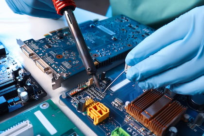
THT - Through Hole Technology - is the technique whereby electronic components are mounted on the board by inserting their metal terminals into metal holes in the PCB. Then, the components are fixed with hands or wave soldering machines, which melt a certain amount of solder to create a "connection" between the component and the conductive part of the PCB, as well as fixing the component to the board.
On the other hand, SMT - Surface Mounting Technology - is the technique whereby SMD (Surface Mounting Device) electronic components are mounted directly on the surface of the board, without the need to drill metal holes in the circuit board. This technology is advantageous it allows the use of miniaturised components with reduced terminals, thus making the circuits adaptable to small devices, which can be used in various application areas.
SLIM, in fact, uses this type of SMT LED electronic board for light signalling switches.
How is the process of making SMT electronic boards on printed circuit boards carried out?
The process of manufacturing electronic boards on printed circuit boards using Surface Mounting Technology consists of several steps that are carried out using an automatic or semi-automatic SMT line, and allow the production of microcircuits.
The SMT line involves a series of interconnected machines, each with a specific function, and highly specialised personnel who set the parameters of the SMT line following the assembly program.
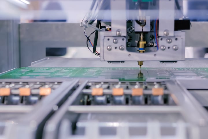
As a first step, the screen printing machine applies solder paste to the metal pads on the surface of the printed circuit boards. In this step, a moving squeegee blade runs over the foil, spreading the solder paste only on the pads of the board. This is an indispensable piece of equipment and is carried out in accordance with the diagram showing the layout of the components.
Next, the printed circuit board is led to the Pick&Place machine which takes the components from the feeders and places them where they are needed. This machine, thanks to a specific program inserted into the computer by the expert personnel, is able to recognise which components to pick up and where to place them correctly.
In order for the electronic components to remain fixed to the circuit, and thus be able to perform their function, the soldering cream must be melted inside the oven at reflow temperature, before solidifying as it cools. This step takes place in the final part of the oven: in this way, at the exit, the board can be handled by qualified personnel for the next control step.
Verification of whether each component has been placed correctly and welded perfectly is done by optical inspection.
The staff carries out manual soldering, the addition of components such as clamps, cables, and the cutting, where necessary. Several boards on a single panel are separated by the cutting. Each electronic board is then tested before any mechanical assembly takes place.
Finally, the finished product undergoes a final functional test before being packaged and shipped to the customer.
In addition to speeding up production, these steps help reduce risk and provide customers with a better quality end product.
Are you looking for a specific light signalling product for your application? Click on the button below and download the SLIM product catalogue to discover the wide range of components available!