The illuminated switch is an electric control device which allows you to establish or interrupt electrical continuity in an electrical circuit. Unlike an indicator light, whose function is to externally display a specific status of the application on which is mounted, the switch allows the operator to intervene directly on the application and modify its status, for example, by opening and closing a specific circuit.
We are talking about an illuminated switch, or more generally, an illuminated control, when a light source is inserted inside it which is then adjusted, based on the type of application, by being switched on or off. In the case of an illuminated switch with a 0-I marking on the button, for example, the light source is usually configured, so that it comes on when the switch button is in position I to signal that the machine is simply switched on or operating, and that the light goes out when the switch is set to 0 to signal that the machine is switched off.
Would you like more information about SLIM light signalling products? Click on the button below to download the free SLIM S.r.l. product catalogue.

- Illuminated switch for panels
- Illuminated switch: the voltage
- Illuminated switch and illuminated diverter
- Illuminated switch: the wiring diagram
- SLIM illuminated switches
Illuminated switch for panels
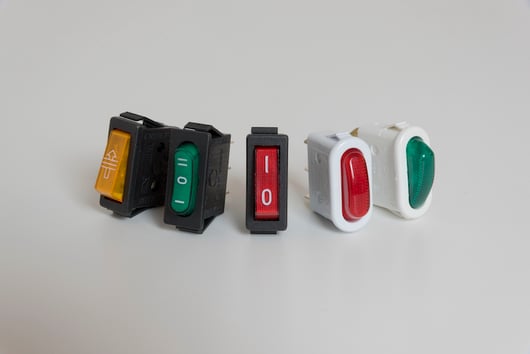
Illuminated switches are devices fastened on panels and used in a variety of applications. The illuminated control is usually fastened by a self-locking system.
The illuminated switch for panels consists mainly of the following components:
- button: it can be in different shapes and sizes and can be marked in various ways depending on the application for which it is intended;
- plastic body: it contains the internal components and is used to allow correct assembly on the application panel;
- internal components: the type of internal components is defined according to the functions that the control must carry out. If the control is single or double pole, these components include the light source which can be included or omitted based on the requirements of the designer of the finished product;
- connection: this consists of metal terminals which allow the electrical connection between the machine circuit and the control;
- accessories: these are the specific add-on devices which are requested in some applications, such as the protection of the button to increase the IP rating of the switch.
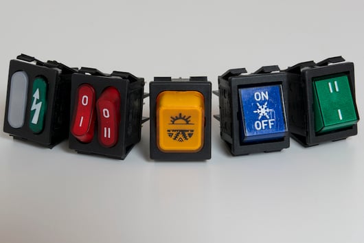
Illuminated switch: the voltage
From a construction point of view of the control device, the choice of the light sources varies depending on whether the illuminated switch needs to operate at a low, medium or high voltage.
Based on the individual requirements, the light sources allocated in the switch can consist of a LED, neon/fluorescent bulb or an incandescent bulb. It is possible to choose the operating voltage ranging from 2V to 400V based on the source and type of control required. The models available include the 12V illuminated switch and the 220V illuminated switch; the voltages which are considered standard are 250V and 110V.
Illuminated switch and illuminated diverter
There are different types of devices which fall under the category of control and can be classified as illuminated or non-illuminated. Switches and diverters are included in this category along with buttons and commutators.
The main difference between a switch and a commutator is the function of the device: the switch opens or closes a single circuit while the diverter opens one circuit while simultaneously closing another.
The switch started out life as a non-illuminated device, but is also used in the illuminated version through the use of a source to indicate the status of a specific appliance, usually to signal that it is switched on. It is unusual, however, to find an illuminated diverter. This device is, in fact, rarely used in the illuminated version because on one position or the other, the appliance is always operating even if in different modes.
Illuminated switch: the wiring diagram
Depending on the result that you want to achieve, the right type of control must be chosen. It is necessary to make a distinction between a single pole switch, illuminated double pole switch and 3-pole illuminated switch.
A single pole switch is a device which interrupts a single pole, or phase, of the electrical connection. A double pole switch, on the other hand, is a device which interrupts the power supply of both the circuit poles called phase and neutral. The illuminated double pole switch is easy to recognise thanks to the typical 0/I marking which, with 0, signals the interruption of the flow of the electrical current and with I, the pole from which the flow starts.
Each of the above-mentioned types (in the single or double pole and illuminated and non-illuminated version), has a specific electrical wiring diagram.
You can also find a vast range of controls in the comprehensive offer of SLIM products.
Depending on the working conditions of the application, SLIM provides different models of illuminated switches with a choice between a single and double pole layout.
To complete the offer of components available to the customer, SLIM also provides the opportunity to customise this product compared to the standard models in the catalogue.
A protective shield can be requested, for example, placed over the button to provide a higher degree of protection, or specific markings can be requested to apply on the buttons to avoid having to rework them before inserting them on the panel of the finished product.
If you are looking for an illuminated switch for your application, click on the button below and contact us, a SLIM expert will be on hand to help you choose the best light signalling product for your needs.